Base Jack is usually considered a temporary structure entered by internal or external workers. Many workplaces are uneven, and adjustable base jacks help to provide a safe and level working surface at a variety of working heights on the ground. A scaffolding leveling jacks is a base jack used to hold scaffolding in place horizontally. The scaffolding leveling jack is mounted on a stable base and contains a large adjustable screw for moving scaffolding up and down. After scaffolding is built, use base jack scaffolding to level the working platform before use. Adjustable U-Head Jacks are designed to be used in conjunction with adjustable system scaffolding. The main function of adjustable U-Head jack is to hold timber beams securely in place.
Other names for base jacks:Scaffolding Jack, Scaffolding Screw Jack, Adjustable Base Jacks, Leveling Jack, Leveling Feet, U-Head Jacks, Base Plate...
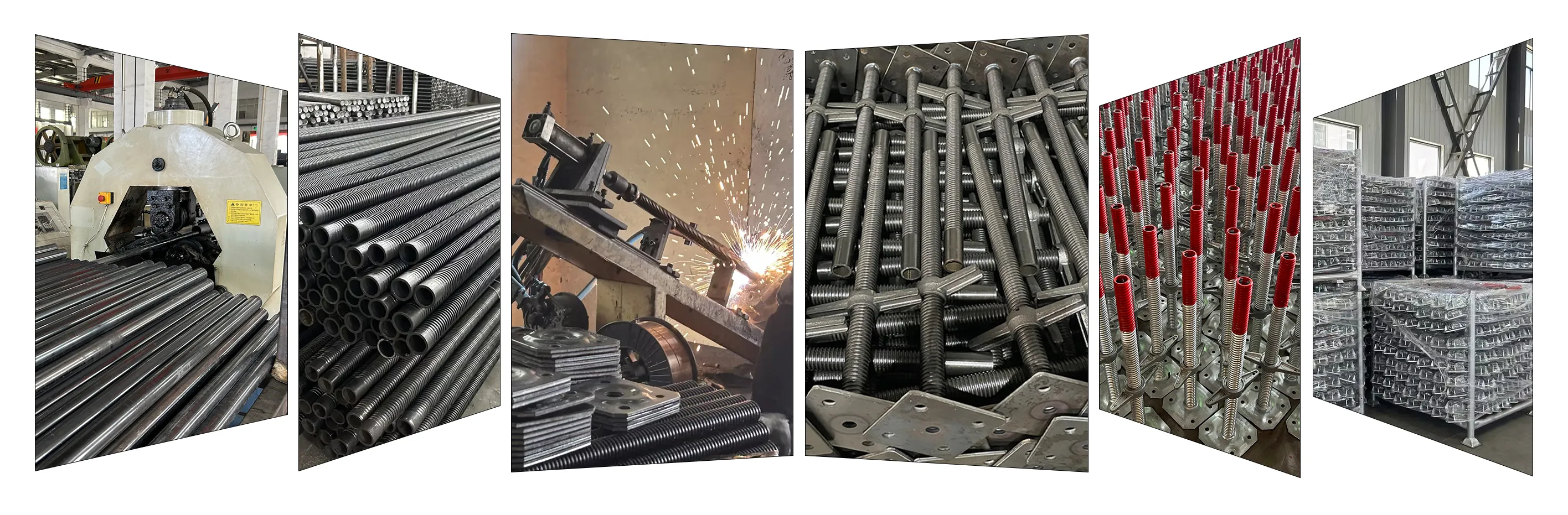
Production Flow
We have a full set of production equipment, including model machine, punching machine, roll machine, sand blasting machine and so on. These production equipment will show how the products are produced, and we can also use these equipment to produce according to your requirements.
Inspection
The professional quality inspection team will carry out strict quality inspection in the production process and before delivery to ensure that the scaffolding jack quality meets customer requirements and improve the positioning of EK scaffolding leveling jacks in the market with high quality.
Packing&Loading
Experienced packing & loading team can effectively monitor the loading schedule of base jack scaffolding, make adjustable base jack arrive at the port of shipment within the scheduled time, and promote customers to receive the scaffolding leveling jacks on time.
Quality Test
According to customers' different requirements, we test the products through the professional third-party quality inspection center according to the data and standards provided by customers, so as to prove to meet customers' requirements.
How To Check If A Base Jack Is Qualified?
1. Weld inspection: The weld between the base plate and the screw must be fully penetrated, without porosity or cracks.
2. Thread inspection: The nut should be able to rotate and tighten smoothly on the screw without jamming.
3. Material certification: A material certificate (Mill Certificate) conforming to standards and a load-bearing capacity test report (SGS) are required.
Images of the Base Jack Quality Produced by EK Scaffolding Manufacturer
What Are The Common Specifications And Adjustment Ranges Of Base Jacks?
scaffolding leveling jacks Classification: ♦ The scaffolding jack is used at the bottom of the vertical steel rod and the bottom plate is at the bottom. The bottom plate can be folded or not folded. ♦ According to the lead screw material, can be divided into hollow base jack and solid base jack. ♦ The screw of hollow base jack is made of thick wall steel pipe, which is light in weight. ♦ The base of solid base jack adopts round steel bar, which is heavy in weight.
Standard base jack specifications typically include:
Screw diameter
30mm, 32mm, 34mm, 38mm (compatible with different standard pipe diameters)
Base plate size
120x120mm, 150x150mm (thickness 5-8mm)
Total length
450mm, 600mm, 750mm, 1500mm (customizable upon request)
Adjustable solid scaffolding screw jack with base plate in 150*150*5mm or customized, screw rod made from high strength steel rod structure with casting or forging scaffolding jack nut for scaffolding system as ringlock scaffolding system, cuplock scaffolding system, kwikstage scaffolding system, haki scaffolding system, tube&fitting scaffolding system and others.
High Load Carrying Capacity Scaffolding Solid Adjustable Base Jack
Name
Base Jack Type
Solid Adjustable Base Jack Size
Solid Adjustable Base Jack Weight (KG)
Screw Rod (MM)
Base Plate (MM)
Solid Adjustable Base Jack
Solid
30*400
120*120*5
3.10
Solid Adjustable Base Jack
Solid
30*600
120*120*5
4.07
Solid Adjustable Base Jack
Solid
32*400
120*120*5
3.39
Solid Adjustable Base Jack
Solid
32*600
120*120*5
4.50
Solid Adjustable Base Jack
Solid
34*400
120*120*5
3.70
Solid Adjustable Base Jack
Solid
34*600
120*120*5
4.95
Solid Adjustable Base Jack
Solid
35*400
150*150*5
4.17
Solid Adjustable Base Jack
Solid
35*500
150*150*5
4.84
Solid Adjustable Base Jack
Solid
35*600
150*150*5
5.51
Solid Adjustable Base Jack
Solid
38*500
150*150*5
5.48
Solid Adjustable Base Jack
Solid
38*750
150*150*5
7.48
Solid Adjustable Base Jack
Solid
45*400
150*150*5
6.04
Solid Adjustable Base Jack
Solid
45*500
150*150*5
7.18
Solid Adjustable Base Jack
Solid
45*600
150*150*5
8.32
Specifications can be customized according to requirements
Scaffolding Hollow Adjustable Base Jack
Scaffolding hollow adjustable base jack made by high strength steel structure in hollow tube diameter 35/38/48mm with screw thread. Usually used at the bottom of scaffolding system verticals, it makes the whole scaffold system more stable.
High Load Carrying Capacity Scaffolding Hollow Adjustable Base Jack
Name
Base Jack Type
Hollow Adjustable Base Jack Size
Hollow Adjustable Base Jack Weight (KG)
Screw Rod (MM)
Base Plate (MM)
Hollow Adjustable Base Jack
Hollow
35*4*600
150*150*5
3.32
Hollow Adjustable Base Jack
Hollow
38*4*600
150*150*5
3.50
Hollow Adjustable Base Jack
Hollow
48*4*600
160*160*6
4.41
Hollow Adjustable Base Jack
Hollow
35*5*400
150*150*5
2.96
Hollow Adjustable Base Jack
Hollow
35*5*500
150*150*5
3.33
Hollow Adjustable Base Jack
Hollow
35*5*600
150*150*5
3.70
Hollow Adjustable Base Jack
Hollow
38*5*500
150*150*5
3.52
Hollow Adjustable Base Jack
Hollow
38*5*750
150*150*5
4.55
Hollow Adjustable Base Jack
Hollow
45*5*400
150*150*5
3.46
Hollow Adjustable Base Jack
Hollow
45*5*500
150*150*5
3.95
Hollow Adjustable Base Jack
Hollow
45*5*600
150*150*5
4.44
Specifications can be customized according to requirements
How To Choose Between Solid Base Jacks And Hollow Base Jacks?
The choice of base jack primarily depends on project load requirements and cost control. It is recommended to match the base jack to the design value of the axial force of a single upright based on engineering calculations, ensuring a safety factor of no less than 2:1.
Solid Base Jacks: Offer extremely high load-bearing capacity and are typically used in heavy-duty support systems (such as for cast-in-place bridge beam construction). They are heavy and highly stable.
Hollow Base Jacks: Made from seamless steel tubing, they are lighter and easier for workers to handle. They are suitable for standard building formwork system and offer good cost-effectiveness.
Scaffolding Adjustable U-head Jack
Scaffolding adjustable U-head jack is designed for use in combination with adjustable system supports. The main function of the Scaffolding adjustable U-head jack is to hold the wooden beam in place. The Scaffolding adjustable U-head jacks we offer are of high quality standard, and these have a pure zinc plated finished, thus adding to its gloss. These are all adjustable and therefore the greatest advantage of these products. This was done under the scrutiny of experts, thus ensuring superior performance.
What Is The Difference Between U-Head Jack And Base Jack?
Although both use screws to adjust height, their functional logic is completely different:
Base Jack: Typically used for bottom support, with a flat steel base, focusing on pressure resistance and preventing settlement.
U-Head Jack: Typically used for top support, equipped with a U-shaped open steel plate, focusing on creating crossbeams and preventing tipping.
What are the standard dimensions of U-Head Jack (U-Plate Jack)?
The dimensions of a U-Head Jack must match the width of mainstream beams (such as wooden or aluminum beams): Standard Width: Commonly 150mm or 170mm. Side Wing Height: Typically 100mm or 150mm, used to prevent the beam from slipping under load. Steel Plate Thickness: Core standards require between 6mm and 8mm to prevent deformation under heavy loads.
Features
Standard U-Head Jack
Heavy Duty U-Head
Screw Diameter
30mm / 34mm
38mm / 48mm
Typical Load Capacity
30 - 50 kN
60 - 100 kN
Packet Shape
Fixed U-Head
Swivel U-Head
Material Grade
Q235
Q345 / S355
High Load Carrying Capacity Scaffolding Adjustable U-head Jack
Name
U-head Jack Type
Adjustable U-head Jack Size
Adjustable U-head Jack Weight (KG)
Screw Rod (MM)
Base Plate (MM)
Solid Adjustable U-head Jack
Solid
30*400
150*120*50*5
3.11
Solid Adjustable U-head Jack
Solid
30*600
150*120*50*5
4.08
Solid Adjustable U-head Jack
Solid
32*400
150*120*50*5
3.40
Solid Adjustable U-head Jack
Solid
32*600
150*120*50*5
4.51
Solid Adjustable U-head Jack
Solid
34*400
150*120*50*5
3.71
Solid Adjustable U-head Jack
Solid
34*600
150*120*50*5
4.97
Solid Adjustable U-head Jack
Solid
38*500
150*120*50*5
5.18
Solid Adjustable U-head Jack
Solid
38*750
150*120*50*5
7.17
Hollow Adjustable U-head Jack
Hollow
30*3.0*400
150*120*50*5
1.98
Hollow Adjustable U-head Jack
Hollow
30*3.0*600
150*120*50*5
2.38
Hollow Adjustable U-head Jack
Hollow
32*3.0*400
150*120*50*5
2.04
Hollow Adjustable U-head Jack
Hollow
32*3.0*600
150*120*50*5
2.47
Hollow Adjustable U-head Jack
Hollow
34*3.0*400
150*120*50*5
2.04
Hollow Adjustable U-head Jack
Hollow
34*3.0*600
150*120*50*5
2.47
Hollow Adjustable U-head Jack
Hollow
38*4.0*500
150*120*50*5
2.86
Hollow Adjustable U-head Jack
Hollow
38*4.0*750
150*120*50*5
3.70
Specifications can be customized according to requirements
Scaffolding Base Plate
Scaffolding base plate is a type of footplated for scaffold system and tube&clamp scaffolding. The spigot for scaffolding base plate can be made from round rod or scaffolding hollow tube. The size of scaffolding base plate can be divided into 50mm, 110mm, 120mm, 140mm, 150mm and so on according to EN74 / BS1139 standard and can customize according to your requirements. Depending on the usage and size of spigot, scaffolding base plate can be in insert type and socket type.
High Load Carrying Capacity Scaffolding Base Plate
Name
Base Plate Type
Scaffolding Base Plate Size
Scaffolding Base Plate Weight (KG)
Rod / Tube (MM)
Base Plate (MM)
Scaffolding Base Plate
Rod
12*80
120*120*5
0.62
Scaffolding Base Plate
Rod
12*100
120*120*5
0.63
Scaffolding Base Plate
Rod
12*80
120*120*6
0.73
Scaffolding Base Plate
Rod
12*100
120*120*6
0.74
Scaffolding Base Plate
Rod
12*80
150*150*5
0.94
Scaffolding Base Plate
Rod
12*100
150*150*5
0.95
Scaffolding Base Plate
Rod
12*80
150*150*6
1.11
Scaffolding Base Plate
Rod
12*100
150*150*6
1.13
Scaffolding Base Plate
Tube
35*3.0*50
120*120*5
0.67
Scaffolding Base Plate
Tube
36*3.0*50
120*120*5
0.69
Scaffolding Base Plate
Tube
38*4.0*50
120*120*6
0.85
Scaffolding Base Plate
Tube
38*4.0*100
120*120*6
1.02
Scaffolding Base Plate
Tube
35*3.0*50
150*150*5
1.01
Scaffolding Base Plate
Tube
36*3.0*50
150*150*5
1.02
Scaffolding Base Plate
Tube
38*4.0*50
150*150*6
1.23
Scaffolding Base Plate
Tube
38*4.0*100
150*150*6
1.40
Specifications can be customized according to requirements
Base Jack Scaffolding "Screw Thread " Production
Components
The Advantages Of A Base Jack.
♦ Material: Q235 round bar or ERW pipe.
♦ Diameter: 30mm/32mm/34mm/38mm/48mm or as your request.
♦ Adjustable Length: From 100mm to 1000mm as your request.
♦ Type: Solid / Hollow for your choose.
♦ Surface Treatment: Black, Paint, Electro Galvanized, Hot Dip Galvanized.
♦ Main Components: Threaded bar, Cast Nut and Base Plate.
♦ Certificate: SGS, CE.
♦ Packing: In Bulk or Steel Pallet suitable for sea transportation or as your request.
♦ Good joint, high efficiency with strong loading capacity.
♦ Leveling jacks with many types of plates.
♦ Simple structures, simple erection.
♦ Widely application for many types of scaffolding system, such as ringlock system, cuplock system, kwikstage system, haki system, frame system and pipe&fitting system.
The Application Of Base Jack Scaffolding.
The base jack scaffolding is widely used in combination with scaffolding systems for building, hall, bridge, high-rise building inside and outside the row of scaffolding, used for electromechanical installation, hull construction, decoration engineering activity platform, building a simple roof, temporary site dormitory, warehouse, temporary observation platform, etc.
How To Install Base Jack To Level The Floor.
If the building is built on expansive soil, therefore, with regular movement, a scaffolding screw jack can replace concrete piers between solid wood columns and girders that support the floor joists.
A scaffolding leveling jacks is a metal support column that can be adjusted to make the floor level. It consists of two heavy steel tubes, one inside the other. The inner tube is threaded and adjusted up and down by turning a large wing nut. scaffolding screw jack are fixed with nails to the underside of the girder and to wooden blocks on top of the concrete wharf.
Here’s How To Install A Scaffolding Screw Jack
1. In this process a hydraulic jack and a short column are used to support the floor.
2. Use hammers, nail pullers and sledgehammers to remove existing supporting posts and nails.
3. Place the scaffolding adjustable scaffolding screw jack under the beams and the wooden blocks on the concrete piers in the middle.
4. Adjust the scaffolding screw base jack so that the top and bottom panels are flush with the top and bottom wood surfaces.
5. Drive the 16 -penny nail through the hole in the plate and into the wooden frame.
6. Lower the hydraulic jack and transfer the floor load to the new scaffolding screw jack.
7. Adjust the scaffolding jack up and down to make the surface smooth.
Centered Holes. A qualified base plate typically has 2-4 pre-drilled holes for securing it to concrete or wooden mats if necessary.
Verticality. The uprights must be fully inserted into the inserts and flush against the base plate surface, with a gap not exceeding 2mm.
1. Missing locating pins: Using a flat steel plate instead of a base plate with insert rods may cause the bottom of the frame to shift laterally.
2. Suspension: Due to slight ground undulations, the base plate may be partially suspended, and the shims may not be properly secured.
3. Insufficient weld strength: The weld between the insert rod and the base plate is only a tack weld instead of a full weld.
Standard thickness: Typically 5mm, 6mm, or 8mm. Risk point: If the base plate is too thin (e.g., < 4mm), "dishing" will occur under concentrated loads, causing the load to concentrate in the center rather than be evenly distributed, thus crushing the wooden pad underneath.
OSHA mandates that scaffolding must be vertical. If the ground slope exceeds 1:60 (approximately 1 degree), OSHA recommends using Base Jacks (adjustable bases) instead of fixed Base Plates to avoid unsafe methods such as leveling with bricks.
Specification: 150*150*50*6/38*600mm or as you Surface Treatment: Black, Electro, Hot-Dip-Galvanized Material: Carbon Steel Q235 Marking: BS1139 / EN74 or as you Standrad: BS Standard
Specification: 150mm*150mm*5mm/38mm*4mm or as you Surface Treatment: Painted, galvanized, HDG, powder coated Material: Q235 or Q345 Marking: BS1139 / EN74 or as you Standrad: BS Standard
Specification: 700mm 35/38*4mm 170*84mm or as you Surface Treatment: Painted, galvanized, HDG, powder coated Material: Q235 or Q345 Marking: BS1139 / EN74 or as you Standrad: BS Standard
Specification: 150*150*50*6/38*600mm or as you Surface Treatment: Black, Electro, Hot-Dip-Galvanized Material: Carbon Steel Q235 Marking: BS1139 / EN74 or as you Standrad: BS Standard
1)Specification:35/38mm or Customized
2)Surface Treatment: Painted, galvanized, HDG, powder coated
3)Material: Q235 or Q345
4)Marking: BS1139 / EN74 or as you
5)Standrad: BS Standard

-封面.jpg")
-封面.jpg")


